

 Released:2026-10-27 10:18:13
 Views 27 次
 总述 故障指示器是安装在中压配电线路上的在线监测终端,可实时监测线路状态,在短路或接地故障发生时完成故障判断、就地指示及远程上报,将传统人工巡线定位时间由小时级缩短至分钟级。由于设备长期运行于无市电的户外环境,对低功耗、高可靠性及抗干扰能力提出了较高要求。芯佰微围绕故障指示器的模拟信号调理与通信接口,提供运算放大器、RS-485及RS-232接口器件,满足不同功耗和精度等级的设计需求。 技术瓶颈剖析 故障指示器长期部署于野外配电线路,既没有稳定市电,又要经历高低温、雷击、浪涌等复

Overview
The fault indicator is an online monitoring terminal installed on medium-voltage distribution lines, capable of real-time monitoring of line status. In the event of a short circuit or ground fault, it performs fault diagnosis, provides local indication, and facilitates remote reporting, thereby reducing the time required for traditional manual line inspection and fault localization from the hour scale to the minute scale. Given that these devices operate continuously in outdoor environments without utility power, they must meet stringent requirements for low power consumption, high reliability, and robust anti-interference capabilities. Corebai Microelectronics offers operational amplifiers, as well as RS-485 and RS-232 interface components, specifically designed for the analog signal conditioning and communication interfaces of fault indicators, catering to diverse design requirements regarding power consumption and accuracy grades.
Analysis of Technical Bottlenecks
Fault indicators are deployed in remote field distribution networks, where they operate without a stable mains power supply and must withstand harsh environmental conditions—including extreme temperature fluctuations, lightning strikes, and voltage surges. Consequently, the overall design of these devices must simultaneously achieve low power consumption, high reliability, and high-precision detection. On one hand, the sensor signals output by current transformers (CTs) or Rogowski coils exhibit low amplitude; thus, the offset voltage, temperature drift, and noise present in the analog front-end can directly affect fault threshold determination. On the other hand, the communication interface must strike a balance between prolonged standby operation and rapid response capabilities, while also possessing robust ESD resistance and immunity to electromagnetic interference, thereby ensuring the long-term stable operation of the equipment.
System Architecture and Operating Principles
The fault indicator consists of five primary components: the sensing front-end, analog signal conditioning, MCU processing unit, status indication and communication module, and power management module; these modules work in coordination to perform line fault detection and status reporting.
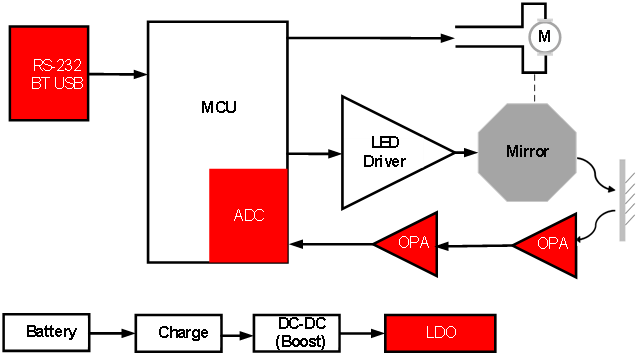
The sensing front-end employs a CT coil or a Rogowski coil to acquire the line current, converting the primary-side current into analog signals ranging from millivolts to volts; the analog signal conditioning circuit utilizes operational amplifiers to perform amplification, filtering, and level matching, ensuring that the signals meet the sampling requirements of the MCU's built-in ADC. The MCU analyzes the sampled data, identifies fault conditions (e.g., short circuits or grounding faults) based on predefined fault criteria, controls an LED to provide local fault indication, and uploads fault information via a 433 MHz wireless module or an RS-485 interface; the RS-232 interface is used for device parameter configuration and field debugging.
Given that the device has long relied on line coupling for power acquisition, supplemented by batteries, supercapacitors, and a power management module to sustain operation, the entire system operates in a low-power monitoring mode for the majority of its runtime. Only when a fault is detected do the indication and communication modules activate; once status reporting is completed, the system reverts to low-power mode. Consequently, the analog signal conditioning circuitry and the communication interface not only determine the accuracy of fault detection but also constitute critical factors influencing the overall power consumption and long-term operational reliability of the device.
Corebai Micro-Solutions
For the most critical components of a fault indicator—namely analog signal conditioning and communication interfaces—Corebai Micro provides device solutions encompassing operational amplifiers, as well as RS-485 and RS-232 interfaces. Specifically, the operational amplifier is responsible for conditioning weak sensor signals; RS-485 is used for wired communication or networking; and RS-232 is employed for field debugging. The ADC is integrated within the MCU, while the power supply system is comprised of a battery, a supercapacitor, and a power management module.
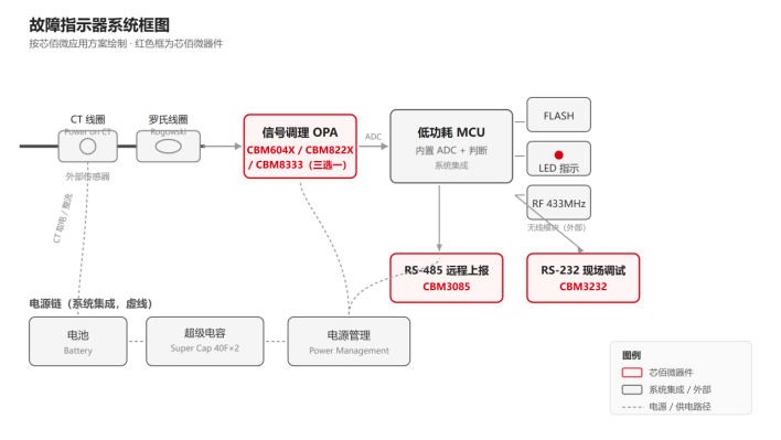
Figure: Block diagram of the fault indicator system
Signal flow: CT coil / Roosch coil → OPA amplifier → MCU built-in ADC → fault detection → local LED indication + RS-485 / RS-232 / 433 MHz telemetry; power supply is provided to the entire system via a battery and a supercapacitor (40F × 2) through a power management circuit.
Recommendations for Analog Front-End Component Selection
Different fault indicator products have varying requirements regarding battery life, measurement accuracy, and sampling strategies; therefore, this solution provides three operational amplifier configurations to facilitate component selection based on the overall system objectives:
1. CBM604X Series (CBM6041/6042/6044) — Signal conditioning with extended battery life as the priority
The CBM6041/6042/6044 models feature a static current of only 600 nA (typical) and a supply voltage range of 1.4 V–5.5 V, making them suitable for low-speed sampling and general fault signal conditioning applications. They are particularly well-suited for fault indicator designs requiring long-term online operation with power efficiency as a priority.
2. CBM8333 Series (CBM8333/8336/8339) — Precision-Prioritized Signal Conditioning
The CBM8333/8336/8339 is a low-power, precision zero-drift operational amplifier featuring: an offset voltage of 30 µV (maximum at 25 °C), temperature drift of 0.05 µV/°C, and no drift in fault threshold determination across wide temperature ranges—thereby reducing false alarms and missed detections; a quiescent current of 25 µA, which is considered low-power among precision devices; and a bandwidth of 350 kHz, providing ample headroom for fault signal processing. This model is ideal for field applications characterized by large temperature variations and stringent requirements for detection reliability.
3. CBM822X Series (CBM8221/8222/8224, S version with shutdown function) — Balancing speed and shutdown control
The CBM8221/8222/8224 series supports fast sampling rates, while the CBM8221S/8222S variants feature a low standby current of only 1 µA, making them ideal for systems that alternate between "fast sampling" and "sleep" modes—requiring on-demand power supply and intermittent operation. With a supply voltage range of 2.5 V–5.5 V and a 500 kHz gain-bandwidth product, these devices offer an optimal balance between bandwidth and power consumption, making them well-suited for analog front-end designs that require periodic sampling and intermittent operation.
All three of the aforementioned product series employ a rail-to-rail I/O architecture and support an industrial operating temperature range of-40 °C to 125 °C, enabling the selection of appropriate models on the same hardware platform based on different product requirements.
|
Overall Objectives |
recommend products |
characteristic |
|
Ultra-low power consumption |
CBM604X |
600 nA quiescent current |
|
high-accuracy |
CBM8333 |
Zero drift, 30 μV offset |
|
General Solution |
CBM822X |
Balancing bandwidth and power consumption |
RS-485: CBM3085 — Remote data reporting, energy efficiency, and anti-static performance
RS-485 serves as the primary communication channel for fault indicator network reporting. Given the large number of nodes and their wide geographical distribution, each transceiver on the bus must simultaneously address power efficiency and lightning protection requirements. The CBM3085 automatically powers off during idle periods, reducing its supply current to 9 µA (typical), which, in conjunction with the overall device's sleep mode, enables controllable network power consumption even when a large number of nodes remain online over extended periods. It features ESD protection against ±15 kV air discharge and ±8 kV contact discharge (IEC 61000-4-2), providing robust protection against lightning induction on overhead lines. The device supports data rates up to 600 kbps for fault status reporting, operates with a supply voltage of 5.0 V ±5%, and has an operating temperature range of −40 °C to +125 °C.
RS-232: CBM3232 — Field Commissioning Interface
Field operators require a reliable debugging interface to configure parameters and read the status of the fault indicator. The CBM3232 features a standard RS-232 interface: 3.3 V (up to 5.5 V) power supply, a transmission rate of 120 Kbps, and a charge pump that requires only four 0.1 µF capacitors to generate the required signal levels, resulting in a streamlined peripheral design. It also provides ESD protection up to ±15 kV (IEC 1000-4-2, air discharge, Level 4), ensuring safe operation during live-line debugging. The operating temperature range is −40 °C to +85 °C.
application scenarios
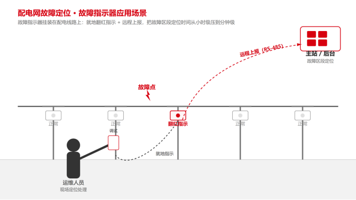
Figure: Application scenario for fault localization in distribution networks (schematic)
On-site fault indicator for medium-voltage overhead lines: The fault indicator is installed on the tower sections of medium-voltage distribution network overhead lines; during a fault, it changes to a red indicator. Line inspectors can then monitor the indicator status along the line to pinpoint the faulty section, eliminating the need to inspect each individual tower.
Remote networking for distribution network automation: Fault status is reported to the data acquisition terminal or master station via communication interfaces such as 433 MHz and RS485; combined with local indicators, this enables both local fault localization and remote aggregation, thereby reducing the time required for fault inspection and resolution. The automatic interface shutdown feature ensures that a large number of nodes remain online over extended periods while keeping power consumption under control.
On-site inspection and commissioning: O&M personnel use the RS-232 commissioning port to configure device parameters and read device status; the ESD interface ensures the reliability of live-line operations.
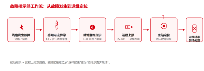
Figure: Fault indicator workflow (schematic)
Core Value of the Solution
1. Facilitates rapid fault localization: The simulated front-end and the communication interface work in synergy to provide reliable hardware support for fault detection, status indication, and data upload.
2. A complete set of components for signal conditioning, data reporting, and debugging: OPA, RS-485, and RS-232 are all provided by Corebai Microelectronics, eliminating the need to interface with multiple suppliers for analog links; the built-in ADC in the MCU also removes the requirement for separate conversion devices, resulting in a more consolidated BOM for the entire system.
3. Select models based on the overall system orientation gradient without requiring redesign: the three op-amp series cater to three distinct requirements—battery life, accuracy, and speed—allowing seamless switching simply by replacing components on the same hardware platform. This approach provides ample flexibility for trade-offs between prototype and mass-production phases.
4. Ensuring reliable operation in harsh field environments: industrial-grade wide temperature range from −40 °C to +125 °C, ESD rating of ±15 kV, and nanocoulomb-level static and automatic shutdown capabilities collectively enable long-duration operation with minimal maintenance.
Quick Selection Reference Table
|
System Location |
Recommended Models |
key parameter |
Role in the complete machine |
|
Signal conditioning (battery life priority) |
CBM604X(6041/6042/6044) |
Static: 600 nA per amplifier; 1.4–5.5 V; 14.5 kHz; offset: up to 3 mV |
Always online, amplifies sensing signals, with negligible power consumption. |
|
Signal conditioning (precision-first) |
CBM8333(8333/8336/8339) |
Offset: 30 µV max; Temperature drift: 0.05 µV/℃; 25 µA; 350 kHz |
The fault threshold determination remains accurate across a wide temperature range. |
|
Signal Conditioning (On/Off) |
CBM822X (8221/8222/8224, S version with shutdown function) |
Bandwidth: 500 kHz; S-version standby current: 1 µA; Supply voltage: 2.5–5.5 V |
Fast sampling rate with intermittent sleep periods |
|
Remote Reporting |
CBM3085 |
RS-485; 5.0 V ±5%; 600 kbps; automatic shutdown at 9 µA; ESD ±15 kV/±8 kV; −40 °C to +125 °C |
Remote reporting of fault status; supports power-saving sleep mode. |
|
Field commissioning |
CBM3232 |
RS-232; 3.3 V (up to 5.5 V); 120 Kbps; ESD ±15 kV; −40 °C to +85 °C |
On-site commissioning port, anti-static |
010-62106066
( Monday to Friday 9:00 - 18:00 )
 704-705, Block D, Building 2, No. 9 Fenghao East Road, Haidian District, Beijing

Wechat Public Account


This app respects and protects the privacy of all users who use the service. In order to provide you with more accurate and personalized services, this app will use and disclose your personal information in accordance with this Privacy Policy. However, this application will treat this information with a high degree of diligence and prudence. Except as otherwise provided in this Privacy Policy, this application will not disclose or provide this information to third parties without your prior permission. This app will update this privacy policy from time to time. By agreeing to this Application Services Use Agreement, you are deemed to have agreed to the entire content of this Privacy Policy. This Privacy Policy is an integral part of this Application Service Agreement.


 Online Store
 A/D Converters (ADC)
 RF Transceiver
 Controller
 Power Management
 Logic gates
 Real-time clocks
 Digital Isolator
 Darlington Transistor
 D/A Converters (DAC)
 Sensors
 Analog Switches Multiplexers
 Interface
 Monitoring Circuit
 Amplifier


 在线商城
